


-
2025-12-18
Well-known sweeper brand
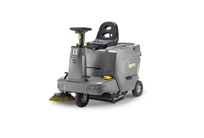
1.KarcherKarcher is a global leader in cleaning technologies, offering a full range of equipment including pressure washers, floor scrubbers, and vacuum cleaners. Known for its innovation and quality, Karcher provides solutions for both home and professional cleaning applications. Its unwavering commitment to sustainability and superior performance has made it a trusted brand worldwide. Ideal for high-traffic commercial and industrial locations.2.TennantTennant is a leading global designer and manufacturer of floor cleaning solutions. Tennant offers a full range of floor cleaning equipment, including walk-behind and ride-on floor scrubbers, industrial floor sweepers, and robotic cleaning machines. Featuring robust and durable manufacturing quality and an extensive service network, Tennant is suitable for large industrial customers seeking high performance.3.NilfiskAnother cleaning equipment giant is Nilfisk. Nilfisk boasts over a century of experience in manufacturing cleaning equipment, with its main products including industrial vacuum cleaners, floor scrubbers, and sweepers. They successfully transitioned from industrial sweepers to street sweepers with their CityRanger series of vacuum cleaners.4.HakoAs a long-standing leader in industrial floor cleaning equipment, Hako's equipment is designed for heavy-duty working environments and is renowned for its superior manufacturing quality. Featuring robust, durable, and high-performance equipment, Hako offers a complete product range.5.ComacComac manufactures professional floor cleaning equipment, including floor scrubbers, sweepers, and vacuum cleaners. Its equipment is designed for high efficiency and practicality, serving industries such as retail and logistics. Comac is committed to innovation, ensuring the delivery of high-quality cleaning solutions. A wide selection of products is available.6.ICEOne of the UK's most trusted brands in the cleaning technology field. Offering both automatic and manual floor scrubbers equipped with intelligent analytics. The Urban 1350 is ideal for urban environments, its flexibility and ease of use helping operators work efficiently in congested areas. This model also offers a variety of application options, including post-cleaning disinfection, making it an ideal choice for urban facilities.7.DulevoDulevo is known for its street sweepers and municipal-grade machinery. Their products are large and powerful, making them ideal for large outdoor areas.8.PowerbossPowerboss scrubbers feature various innovative technologies. This guaranteed unmatched floor scrubbing and cleaning.They come in two models – the ride-on and walk-behind models. Both Powerboss models are meticulously designed to improve operator comfort and performance.9.IPCIPC Group designs and manufactures a wide range of cleaning equipment, including floor scrubbers, sweepers, and carpet cleaners. Their equipment is designed to be durable and have a long service life.10.MACThe professional floor cleaning range from MAC International offers high-performance commercial floor care equipment, including pedestrian and ride-on sweepers and scrubber driers, designed for exceptional floor care.Is BOSA ENERGY the right LiFePO4 battery supplier for sweeper?Bosa floor sweeper LFP battery packs use class A batteries, safer, more reliable and have a longer cycle life(>3500 cycles), can provide long-lasting and stable power support.It can be flexibly adapted to a variety of sweeper models.Why choose us?Charging: fast and flexible. Can be charged at any time, won't damage the battery.Durability: handles the bumps and jolts of daily life.Maintenance: No watering required. No acid. No corrosion. No acid drips. No charging fumes.Safety: Stable LiFePo4.Range: goes the distance.Famous battery systems of BOSA ENERGY.
 See more —>
-
12-042025
Top 10 Golf Cart Brands by 2025
1. Club CarA perennial leader in the industry, Club Car continues to be a top golf cart manufacturer known for its robust construction and wide range of models.Their models, like the Onward series, are highly regarded for their customization options and premium features, making them a popular choice for both personal and fleet use.2. YamahaYamaha brings its world-renowned Japanese engineering and manufacturing precision to the golf cart market. Known for its quiet and smooth-riding gas-powered models, such as the Drive2 PTV, Yamaha is also making significant strides in electric technology. Their focus on superior suspension and a comfortable ride experience sets them apart as a top golf cart brand.3. EZ-GOE-Z-GO has built a strong reputation for producing reliable and efficient golf carts. As part of Textron Specialized Vehicles, E-Z-GO benefits from a long history of engineering excellence.Their vehicles are praised for their durability and performance, with models like the Freedom and Express series offering a variety of options for different applications, from the golf course to the neighborhood.4. EvolutionEvolution has rapidly become a beacon of innovation in the electric vehicle sector. With a global presence and a dedication to cutting-edge design, Evolution’s carts go beyond traditional golf course use. Their models, like the D5 series, feature modern technology like touchscreen displays and lithium batteries, making them ideal for neighborhood transportation and recreational use.5. ICON EVIcon EV is a newer company that has quickly gained traction by offering high-quality, street-legal golf carts at competitive prices. With a range of models designed for both personal and commercial use, Icon EV is making a name for itself with its modern designs and standard features that are often optional extras on other brands.6. Cushman VehiclesCushman specializes in utility and commercial vehicles, offering powerful and practical solutions for a variety of tasks. Their Hauler and Shuttle series are designed for heavy-duty work and are commonly found on large golf courses, in industrial settings, and at large-scale events. Cushman’s focus on durability and functionality makes them a top choice for businesses and organizations that require a reliable workhorse.7. GariaFor those seeking the pinnacle of luxury, Garia is the go-to brand. Acquired by Club Car in 2022, Garia is known for its high-end, street-legal golf and leisure cars. Inspired by the automotive industry, Garia vehicles feature premium materials, Italian drivetrain technology, and award-winning design. They are the definition of a luxury golf cart brand, targeting resorts, high-end residential developments, and discerning private owners.8. Star EVStar EV is an American manufacturer of low-speed electric vehicles, including golf carts and utility vehicles. Known for its focus on sustainability and quality, Star EV provides a range of options for personal and commercial use. Their models feature advanced components and are designed for a smooth and efficient ride.9. TaraFor nearly two decades, tara has been redefining the golf cart experience — combining cutting-edge engineering, luxury design, and sustainable power systems10. TomberlinTomberlin has a reputation for building safe and feature-rich neighborhood electric vehicles. Their golf carts are often street-legal from the factory, equipped with automotive-style safety features like seat belts, turn signals, and a 4-wheel braking system. Tomberlin’s commitment to safety and innovation has earned them a loyal following.
-
11-282025
Why do most balcony energy storage systems choose LFP?
Why LFP is the default choice for balcony energy storage:Safer: Material safety,Suitable for balconies and other locations close to living areas.Long lifespan: Commonly boasts a cycle life of ≥3000 cycles, resulting in an exceptionally long service life.The lifespan can be further extended through temperature control and BMS optimization.Highly economical: Predictable degradation curves reduce uncertainty in LCOS (Levelized Cost of Storage) and IRR (Internal Rate of Return).Compliance-friendly: Complies with mainstream safety and transportation standards.Key Design Considerations for LFP Balcony Energy Storage SystemsModules and Packs: For home storage/balcony use, a typical 0.5C charging and 1C discharging peak value is sufficient; the standardized shape facilitates railing/wall mounting.BMS(Battery Management System):Functions: Balancing, overcharge/over-discharge/over-temperature protection, etc.Thermal Management:For direct sunlight on balconies/high temperatures, prioritize natural heat dissipation + heat conduction channels; for cold regions, add heating film/low temperature strategy to ensure power and lifespan.Electrical and grid connection coordination:For balconies with a large number of micro-reverse connections, AC coupling is the most suitable connection in the short term; DC coupling is more efficient in the medium to long term.Safety and fire protection:DC arcing detection, surge protection, internal temperature/smoke detection, IP65+ shell and flame-retardant materials.
-
11-212025
What is the battery charge cycle life?
There is only one criterion for a true complete charge cycle: the battery's cumulative discharge reaches its rated capacity. Simply put, it means that the total amount of electricity discharged from a fully charged state is exactly equal to its standard capacity (such as 60kWh or 80kWh). This is what constitutes a complete cycle, and it has no direct relation to the number of times the battery has been charged.Key factors affecting battery cycle lifeDepth of discharge: Don't wait until the "red light" comes on before charging!Temperature and storage: Avoid direct sunlight during summer and then fast charge; don't fully charge when parked for an extended period!High temperatures are the enemy of batteries, and storage methods are also crucial:High-temperature protection: Fast charging after exposure to direct sunlight in summer will accelerate battery degradation. It is recommended to charge in a cool, shaded place.Long-term storage: When traveling or on vacation and not using the car, do not store it at full charge. Maintaining 50%-60% charge is optimal.Many car models and charging stations now come with safety featuresmany models allow you to set a charging limit. Setting the limit according to your car model's recommendations can help avoid overcharging.